The project
For the past few years, I have been buying various types of lighting for my back garden trees. I have 5 trees in a row, flattened and interwoven into a flat surface, spanning about 12 x 2 meters of my plot’s border, perfect for chistmas lights.
I have had traditional, incandescent lighting a few years, and LED lighting other years. Last year, I had a single string of 100m with 1000 white LEDs lighting things up. But over the past few years I have seen some cool projects using WS2811, a.k.a. NeoPixels. I thought it might be fun to use them to light my trees this year.
Then I stumbled on this product on aliexpress. It’s a string of pingpong-ball sized balls, lit by a single RGB led, driven by a ws2811 chip. So I decided to make this year’s garden lighting project a 500-pixel full RGB matrix that would span all of my 12×2 leaf cover from my trees.
It now runs at a magestic 32 frames per second, and can play any AVI or OpenGL effects in real time.
Source AVI: https://www.youtube.com/watch?v=sbQhgEJuExY
Key components
The stuff I’m using to do this:
- A Single 400W 12VDC outdoor power supply from amazon (EUR59)
- 10 x 50-lamp strings from AliExpress, with custom lamp spacing (25 cm instead of 12 cm) (USD27 each from aliexpress – see above)
- A single, old, laptop
- Custom electronics (yes, soldered some stuff onto a PCB)
- Lots of power cord, splitter boxes, connectors, etc
- A big, waterproof box to put all the electronics in
- Hot glue (one lamp wasn’t properly waterproofed – still pretty good with 499 of them working fine for weeks in the rain & cold)
Driving the signal
One of the main points of this project was to be able to drive the ‘display’ at a high framerate. Most of the projects you can find on the internet using NeoPixels have some kind of lame effect or very low framerate, while the pixels themselves are capable of doing full color, 24 bit, 33 frames-per-second video (when you have 500 of them). I also wanted to make sure my video had no tearing or jittering, and I wanted antialiasing to make things looks smooth.
To drive the LEDs, you need to produce a 400kbit/sec signal. The signal itself is quite simple; each pixel’s data is output sequentially, each pixel takes 24 bits, each bit is a HIGH/LOW combination on the data line, with differing timings for HIGH and LOW depending on whether you want to output a 1 or a 0. Sounds simple enough.
So all you need is a something to generate that signal. Now 400 kbit/sec isn’t very much even for 10-year-old PC’s, but you need to find some way to output it in the right format without having to buy specialist hardware. There are several options to do this directly from your PC like using your parallel port (if you have one) or maybe using your audio port.
But there is one more output port. It’s easy to use, most computers have one, and the spec is clear: it’s your VGA port.
Using VGA port as general-purpose DAC
Most people know that VGA is analogue; it predates the digital DVI and HDMI standard. VGA is actually very, very simple. It essentially has 5 output pins (the other pins on your 15-pin VGA connector are used for autodetection and ground):
- Red, Green, Blue
- H-Sync
- V-Sync
What happens when sending a signal to your monitor is that your VGA card sends a signal, starting top-left scanning right, which is HIGH when things should be bright (eg RED) and LOW when it’s dark (eg black). So a row of alternating black and white pixels would generate an alternating HIGH and LOW signal. Then, at the end of each scanline, it tells the monitor to go to the next line. It does this by sending a HIGH signal on H-Sync, at which point the computer startes outputting the next scanline, and at the end of the frame (the bottom of the screen), it sends HIGH to V-Sync to tell it this is the end of the frame, and we can start over.
So, if your screen is completely white, then R, G, and B will all be HIGH, all the time, and H-Sync and V-Sync will pulse regularly (at about 40 kHz and 60 Hz, respectively, depending on resolution and settings)
So now we want to use this to push the signals we need to power the WS2811. Well, each bit for the ws2811 is 1/400khz = 2.5 uSec long. And for a ‘1’ we should send HIGH for 1.3 uSec, and LOW for 1.2 uSec. (and for a ‘0’, we should send HIGH for 0.5 uSec, and LOW for 2.0 uSec)
That’s easy enough. To output a ‘1’, I can draw a few pixels on my screen, horizontally, and place 13 white pixels and 12 black pixels. That would give us a signal on Red, (and Green and Blue) which looks about right, since that would map to HIGH, LOW.
That’s not quite right though. Depending on the resolution you’re using, it will take longer or shorter than the requried 2.5 uSec to output those 25 pixels. So I did some math and came up with a nice resolution to use that fits the timing requirements.
What I ended up using was:
- Resolution: 840 x 1000
- Dot clock: 28 MHz (interestingly, this is a frequency that was supported by IBM’s original VGA standard, back in the 90’s)
This means the VGA card will output 28 million pixels per second. This gives me 28M / 400K = exactly 70 pixels for each WS2811 bit. And 840/70 = exactly 12 bits per scanline. So each scanline of my frame will represent 12 bits, and for 500 LED’s I need 500 x 24 = 12000 bits, which is 1000 lines, hence the 1000 lines in the resolution.
This gives me a refresh rate of 28M / 840*1000 = 33.33 frames per second.
And all I have to do to output all of the data for all of my LEDs is to ‘show’ something on my screen and send it to VGA. Simple as that! In fact, in first tests, all I did was show a pre-generated PNG in full-screen on my VGA output, and connect the VGA to the WS2811 string.
It is really that easy?
Hm, no, not really. There are three problems:
- Hsync. VGA wasn’t made to continuously output data on R, G and B, since there is a ‘blanking period’ at the end of each scanline, which breaks my timing
- VSync. Same thing, but after the last line. And this interval is a lot longer
- Voltage levels. VGA uses 0.7V peak-to-peak. This means that at full-on White, the voltage on the VGA port is 0.7V. And my LEDs are expecting 5V at HIGH. That is certainly not going to work (Trust me, I tried)
Fixing the HSync
This was actually relatively easy to solve. It turns out that most video cards will allow you to drive them with very, very short horizontal blanking periods. My NVidia Quadro allows me to output a blanking period of exactly one pixel ‘wide’. So at the end of each scanline, it will output one additional ‘black’ pixel. Since the last pixel I want to output is always black anyway, there is a good chance that the ws2811 will just accept this minor timing deviation, but just for good measure I changed the resolution to 839 x 1000, so now the effective resolution being output is the required 840 x 1000
Fixing the VSync
Turns out this is not a problem at all, really. In fact, it is a very useful feature. This is due to a feature of the WS2811 protocol I had not discussed yet.
The data that you send to WS2811 isn’t actually displayed by the LED’s until you send them a ‘show it’ signal. The ‘show it’ signal is sending a LOW signal for more than 50 uSec. Well, that’s great, because the vertical blanking period is LONG. Much longer than 50 uSec. So actually, this is perfect, since after sending all my bits, the VSync will automatically output a LOW signal for more than 50 uSec and tell the LED’s to show my frame. The awesome thing about this is that all my LEDs will almost synchronously ‘show’ the new frame, instead of the LEDs updating at different times depending on their position.
Fixing the voltage levels
Now this was the hard part for me. And it wasn’t hard because it was a huge electrical problem to do this, but it was hard because I know little about electronics. So I got myself a cheap, high-resolution oscilloscope, a breadboard, lots of electronic components, wires, the whole shebang, and read wikipedia and random websites in an attempt to try to remember how transistors worked. And capacitors. And resistors.
Then I started to attempt to build an analogue amplifier that would boost my 0.7V signal to 12V which was the voltage I have from my power supply, assuming that 12V would work equally well as 5V.
After much trial-and-error, some help from the local electronics shop, and downloading a software simulation tool (which turns out to be a lot quicker than breadboarding stuff), and came up with a circuit:
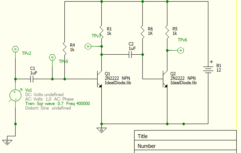
(in this image, Vs1 is the signal source, and TPv6 is the output). Short story: two inverting npn amplifier circuits in series, with an input bias resistor (R4, R6) to overcome the transistor’s forward voltage.
This is what it looks like on a breadboard:

And then, using classic shoddy soldering, on a PCB:

So that’s it?
Well, almost.
Apparently is it a well-known fact of the ws2811 community that you can’t just serially connect ten strings of LEDs and expect them to be powered from one end, or even both ends of the composite string. It turns out that when you put 12V at the start of the string, after 100 LEDs (2 strings), only 6V is left at the end, even though all of the LEDs are wired in parallel. This is just because of wire resistance and the relatively large current that you need (about 6A for 100 LEDs).
Looking around on the internet, it looks like you can buy special power injection splitters, that expose your + and – but connect through the data line, so you can ‘inject’ power at regular intervals.Shipping cost was rather high (to europe) on these products though, so I decided to bodge some together myself, went to local hardware store and bought waterproof power boxes, and connectors from a local online retailer. This gave me boxes looking like this:

The left side takes a 3-pin connector from the LED string, and you connect the next string on the right. At the bottom is a 2-pin connector to which you connect your fresh 12V supply.
In the end I had 4 of those boxes, running power lines straight back to the power supply, so power was provided before LED 0, 100, 200, 300 and 400. In hindsight I should have added power to the end of the line as well, after LED 500, since at full-on WHITE for all LED’s, the last 10 LED’s or so go a bit orange. That said, you rarely have all LEDs at white at the same time, since 400W of LED light is quite bright for your back garden.
I also found a nice and easy way to connect my VGA to my home-built amplifier; in the old days, VGA monitors sometimes came with BNC connectors. There would be 5 BNC connectors, one for each of the signals I described above (R, G, B, HSync, VSync). So I bought a VGA-to-BNC connector, they are easy to find and cheap and certainly make it much easier to handle than those 15-pin D-sub VGA connectors. All I need is the R channel, so I leave the other 4 channels disconnected
Software
So, now I have all the hardware I need, next is to find an efficient way to generate the framebuffer that I need to ‘display’ on my VGA port. It looks something like this if you just look at it on a normal display:

The software I use is:
- Ubuntu 15.10 (or something like that)
- X Windows
- Python
- OpenGL
System setup
I wanted to use Linux so I could SSH to my christmas lights in the garden. So I installed ubuntu and proceeded to spend hours trying to figure out how to get X-Windows to have a separate output just for the VGA, to force it to output on VGA even though there wasn’t a monitor connected, and to get it do use my magic 839×1000 resolution.
I ended up using NVidia’s own drivers (not the open source ones, although in hindsight I think that would work too), used an ‘old-style’ multi-screen configuration (so, no Xinerama or NVidia TwinView), which gives me my normal (laptop) display on :0.0 and my VGA output on :0.1.
Here’s the interesting bits from my X Windows config:
Section "Monitor"
    Identifier     "Monitor0"
    VendorName     "Unknown"
    ModelName      "Unknown"
    HorizSync       28.0 - 33.0
    VertRefresh     43.0 - 72.0
    Option         "DPMS"
EndSection

Section "Monitor"
    Identifier     "Monitor1"
    VendorName     "Unknown"
    ModelName      "Unknown"
    HorizSync       28.0 - 100.0
    VertRefresh     20.0 - 100.0

    Modeline "840x1000" 28 839 839 839 840 1000 1001 1004 1018 -HSync +Vsync
EndSection

Section "Device"
    Identifier     "Device0"
    Driver         "nvidia"
    VendorName     "NVIDIA Corporation"
    Screen         0
EndSection

Section "Device"
    Identifier     "Device1"
    Driver         "nvidia"
    VendorName     "NVIDIA Corporation"
    Screen         1
    Option         "ConnectedMonitor" "DFP,CRT"
EndSection

Section "Screen"
    Identifier     "Screen0"
    Device         "Device0"
    Monitor        "Monitor0"
    DefaultDepth    24
    Option         "NoLogo" "True"
    SubSection     "Display"
        Depth       24
    EndSubSection
EndSection

Section "Screen"
    Identifier     "Screen1"
    Device         "Device1"
    Monitor        "Monitor1"
    DefaultDepth    24
    Option         "NoLogo" "True"
    SubSection     "Display"
        Depth       24
        Modes      "840x1000"
    EndSubSection
EndSection

Section "ServerLayout"
    Identifier     "Layout0"
    Screen      0  "Screen0"
    Screen      1  "Screen1" rightOf "Screen0"
    InputDevice    "Keyboard0" "CoreKeyboard"
    InputDevice    "Mouse0" "CorePointer"
EndSection
You can see the magic 840×1000 modeline there that is actually 839×1000, with 1 pixel of horizontal refresh. For V-Sync, it is outputting lines 1000-1018 as blank, which is much longer than 50 uSec. In fact, one line would be enough, and that would give me a slightly higher frame rate.
I read somewhere that somebody found that most VGA cards support these timings, so I have a fair hope that this actually works on more than just my computer.
Rendering
Drawing a pattern like this is easy; you can just draw some lines or boxes in the right place. Still, with 400000 bits to render, that’s 400000 lines or boxes to draw for each frame. That is certainly possible, but you’d probably have to do quite some work to get it to perform at 33 frames per second.
Since I know a bit of OpenGL and GLSL, I decided to write the whole thing in Python and OpenGL. The nice thing about this is that I can offload the generation of the data pattern that is shown above to my GPU using GLSL, since this kind of workload fits the GPU very well; all of the rendering can be parallelized over the GPU’s rendering cores.
The general method is:
- Render whatever you want to show on an offscreen framebuffer object (FBO) on a relatively high resolution (I used 512 x 128) in the ‘normal’ way
- In the final pass, render a full-screen square using the custom ws2811 shader to output the correct pattern
The interesting part is the GLSL shader, which looks like this (note hardcoded resolution of 50 x 10 pixels, and 1000 scanlines):
        #version 150

        uniform sampler2D tex;
        out vec4 f_color;
        in vec2 v_texcoor;

        void main()
        {
            int y = int(v_texcoor.y * 1000);
            int pixel = y / 2; // Each pixel spans 24 bits = 2 lines
            int subpixel = y % 2; // First or second 12 bits

            int bit = int(v_texcoor.x * 12); // 12 bits per scanline
            bit += int(subpixel * 12); // second scanline

            // Where to sample from. Inject exact positioning here when we have it
            float sourcex = (float(pixel % 50) + 0.5) / 50;
            float sourcey = (float(pixel / 50) + 0.5) / 10;

            // Reverse odd scanline sampling locations for snake trail
            if ((pixel / 50) % 2 == 1)
                sourcex = 1 - sourcex;

            // Use Lod = 3, which is 3rd Mipmap (8x8 sample) for antialiasing
            vec3 t = textureLod(tex, vec2(sourcex, sourcey), 3).rgb;

            t = pow(t, vec3(2.2)); // Gamma correction

            int ledvalue = int(t.r * 255); // First 8 bit (R)
            ledvalue = ledvalue << 8;
            ledvalue |= int(t.g * 255); // Next 8 bit (G)
            ledvalue = ledvalue << 8;
            ledvalue |= int(t.b * 255); // Next 8 bit (B)

            int bitvalue = (ledvalue >> (23 - bit)) & 1; // The bit we want

            float bitoffset = (v_texcoor.x * 12) - (bit % 12);

            float color;

            if(bitvalue == 0) // Outputting a 0
                color = bitoffset < 0.1 ? 1 : 0;
            else // Outputting a 1
                color = bitoffset < 0.48 ? 1 : 0;

            f_color = vec4(color, color, color, 1);

        }
In this implementation, I also do the following:
- Anti-aliasing: Since I have so few pixels, you want to smooth (blur) the incoming signal. This makes video look much better. OpenGL makes this very easy using level-of-detail (Lod) control when sampling the incoming image.
- Gamma correction: The VGA standard uses a gamma correction factor of 2.2. The WS2811 LEDs have a gamma of 1.0. Not doing this gives you much too bright results and very bad contrast
- Snake trail: the LEDs on my tree traverse it like a snake. It starts bottom-right, then goes to bottom-left, then goes up one line, and back to the right. This means odd lines are mirrored while even lines are not.
Update 4-1-2016: Code posted to github
Improvements
I still have the following possible improvements to make:
- Use the other color channels; I’m only using the Red channel at the moment, but Green and Blue are still free. This means I could add another 1000 LEDs and still have the same frame rate (33 fps)
- The LEDs are not perfectly placed in my trees. I didn’t really take the time to make sure they were in a perfect matrix. In fact, some of the scanlines are off-by-one-pixel. To compensate, I could take a camera, turn each LED on one by one, and record their position. Then I can take the actual position of the LED into account when generating the signal. This is relatively easy once you know the positions of the LEDs, since the shader can just look up the position and compensate accordingly. And this should work wonderfully with the existing antialiasing.
- Use WS2812 LEDs. WS2812’s run at 800KHz, double the speed of the 2811’s. This means twice the framerate. Modifying the setup to support that would be a software-only affair (35 pixels per bit instead of 70).
- I’m using a full-blown PC to do this, but most of the work is done by the GPU. It should work fine on an SoC-type of system like the Raspberry Pi or an android-based HDMI stick. However, these systems only have HDMI outputs. Logically, HDMI and VGA are closely related; even the VGA timing is transmitted on HDMI. It may be possible to put an HDMI-to-VGA converter in between and run it from that. But it is unclear if this will mess up the timings inside the converter (most notably, the very short HSync). I guess that depends on how ‘smart’ the converter is.

I will post a link to the code once it is an a state that I feel it is useful for others 🙂
LikeLike
Nice Steve!
Maybe add an e-mail interface to it?
LikeLike
http://hackaday.com/2016/01/02/czech-out-raspberry-pi-riding-the-rails/
Or something like this 😀
LikeLike
The newer Raspberry Pi’s (B+ onwards, with the 40 pin header) have the ability to output digital VGA (18 bits plus syncs) through the GPIO header. It’s intended to feed a resistor ladder DAC, but you could run each pin directly by setting the appropriate bit of each pixel. You’d be able to run a ridiculous number of LEDs off such a setup…
https://www.raspberrypi.org/blog/gert-vga-adapter/
LikeLike
that sounds awesome!
LikeLike
Nice! looking forward for the code
LikeLike
https://github.com/sharky5102/ws2811vga
LikeLike
Hi Steve
Wonderfully written blog about this smart integration project! We need integration projects like these to surface more often. Thank you for inspiring me!
😀
LikeLike
What about separating circuit into three parts, every connected to one color channel? Then you can use 1/3 resolution => 3x higher framerate 🙂
And nice circuit by the way, I think you could also use some comparator IC – you can get four comparators in one package (LM339 comes to my mind) and I guess it should work same way as your circuit, but being more compact (one IC with few resistors around).
LikeLike
I’m currently working on the raspberry pi 2b solution using digital VGA pins giving 24 output channels. That would give me a framerate of 720 🙂 … or a display of 12000 LEDs at 30fps. But that would need about 10 kW of power, hmmm.
The LM339 looks great! I had tried the LM318 but that only works with a dual power supply (as I learnt after breadboarding that thing for a few hours)
LikeLike
WOW, that’s pretty fast! o.o Don’t forget to make video with at least HD camera at 60FPS, it will look great on Youtube!
How are you going to control it? I guess you’ll use DMA on array of values and change them as you need? No, I never tried it, just heard somewhere online it’s good way to go 😀
Glad you like it 🙂 But don’t forget to add that 1k resistor between every output and positive rail – it seems like it can only pull output low. But…if you’re going to use Raspberry with 3.3V on GPIO…what about optocouplers? One optocoupler with two resistors per channel should work at first try and you’ll also get isolated outputs, which is always good thing 😉
And I see, that reminds me my fights with LM1458 for hours in simple circuit with no success…then I replaced it with LM358 and everything started to work fine.
LikeLike
Did you get this working? I am trying to do something similar, but with some extra hardware. Your way sounds simpler!
don
LikeLike
I started working on it. Hardware seemed to work as intended but the pi was lacking some gpu software features. I think it would have been possible with some opengl changes. Since I already have a working pc based solution I didn’t proceed
LikeLike
Thank you for this brilliant article! I got it working on a RPi 2 using the dpi24 overlay to send the VGA signal to the GPIO pins without an extra ADC circuit, just some level shifters.
Using this approach, it can drive 24 strings of WS281X nodes in parallel – up to 24 x 550 nodes at 60 FPS, or 24 x 1100 nodes at 30 FPS.
LikeLike
That is awesome! Pics!
LikeLike